Building Information Modeling (BIM) has revolutionized the architecture, engineering, and construction industries, and Autodesk Revit stands at the forefront of this transformation. One of the powerful features within Revit is the ability to create arrays—repetitive patterns of elements that save time and enhance design precision. When it comes to designing LED displays, whether for commercial signage, stadium scoreboards, or architectural installations, understanding how to effectively use arrays in Revit is crucial.
This article explores the concept of arrays in Revit with a specific focus on LED displays. It delves into the technical and design considerations, practical applications, and best practices to help professionals leverage Revit’s capabilities for LED display projects.
Understanding Arrays in Revit
Arrays in Revit are a fundamental modeling tool used to replicate elements systematically along a linear or radial path. Unlike manual duplication, arrays allow users to control the number of copies, spacing, and orientation dynamically, which is essential for maintaining consistency and accuracy in complex models.
There are two primary types of arrays in Revit:
- Linear Arrays: Elements are duplicated along a straight line with equal spacing.
- Radial Arrays: Elements are duplicated around a central point, forming a circular pattern.
For LED displays, linear arrays are most commonly used, as LED modules or pixels are typically arranged in grid-like formations. Radial arrays might be applicable for circular or curved LED installations.
Why Use Arrays for LED Displays?
LED displays consist of numerous identical modules or pixels arranged precisely to form a coherent visual output. Manually placing each LED unit in a model would be inefficient and prone to errors. Arrays automate this process, ensuring uniform spacing and alignment, which is critical for accurate visualization and fabrication.
Moreover, arrays in Revit allow for easy modifications. If the size or resolution of the LED display changes, designers can adjust the array parameters without remodeling the entire display, saving significant time and reducing the risk of inconsistencies.
In addition to efficiency, using arrays can significantly enhance the design process. By leveraging the array functionality, designers can experiment with different configurations and layouts quickly. For instance, if a designer wants to visualize how an LED display would look with varying pixel densities or different spacing, they can simply modify the array settings and instantly see the changes reflected in the model. This flexibility not only fosters creativity but also aids in making informed decisions based on visual feedback.
Furthermore, arrays can be linked to parameters that control their properties, such as visibility or material assignments. This means that if a specific design requirement changes, such as the need for a different color or finish for the LED modules, the designer can update the parameter once, and all instances within the array will automatically reflect this change. This level of control and automation is particularly beneficial in large projects where numerous LED displays are involved, ensuring that the design remains coherent and aligned with the overall project goals.
Technical Considerations for Modeling LED Displays in Revit
Modeling an LED display in Revit involves more than just creating an array of elements. Designers must consider the physical characteristics of LED modules, electrical connectivity, structural support, and integration with other building systems.
Defining the LED Module Family
In Revit, elements are created from families—parametric components that define geometry, materials, and behavior. For LED displays, the LED module should be modeled as a family with parameters such as dimensions, pixel pitch, power requirements, and mounting details.
Creating a detailed LED module family allows for accurate representation in the model and facilitates scheduling, cost estimation, and clash detection. For instance, including parameters for pixel pitch (the distance between the centers of adjacent pixels) is essential for ensuring the display meets resolution requirements. Additionally, designers should consider the thermal management of the LED modules, as overheating can lead to reduced performance and lifespan. Incorporating cooling solutions, such as heat sinks or ventilation pathways, into the family can enhance the reliability of the display over time.
Array Configuration and Spacing
Once the LED module family is ready, the array tool can be used to replicate the module across the display area. The spacing between arrayed elements must correspond to the physical pixel pitch or module size to ensure realistic modeling.
Revit’s array tool allows users to specify the number of copies and the distance between them. For example, a 10×10 LED matrix can be created by applying a linear array in one direction, then grouping the array and applying a second array perpendicular to the first. This nested array approach is efficient for creating large, grid-like LED displays. Furthermore, designers should also consider the viewing angles and distances when configuring the array, as these factors can significantly affect the visibility and effectiveness of the display in its intended environment, such as a stadium or a retail space.
Incorporating Electrical and Structural Elements
LED displays require power and structural support, which should be integrated into the Revit model for comprehensive coordination. Electrical conduits, wiring trays, and power supplies can be modeled as linked families or system components.
Structural elements such as mounting frames, brackets, and support beams must be designed to accommodate the weight and configuration of the LED modules. Using arrays for these components ensures alignment with the LED modules and simplifies design changes. Moreover, it is crucial to account for the load distribution on the structural elements, as uneven weight can lead to structural failure. Including detailed calculations for load-bearing capacities and incorporating safety factors into the design can help mitigate risks. Additionally, integrating maintenance access points into the structural design will facilitate easier servicing of the LED display, ensuring longevity and optimal performance in the field.
Practical Applications and Examples
LED displays are ubiquitous in modern architecture and urban environments. Understanding how arrays in Revit facilitate their design can enhance collaboration and project outcomes.
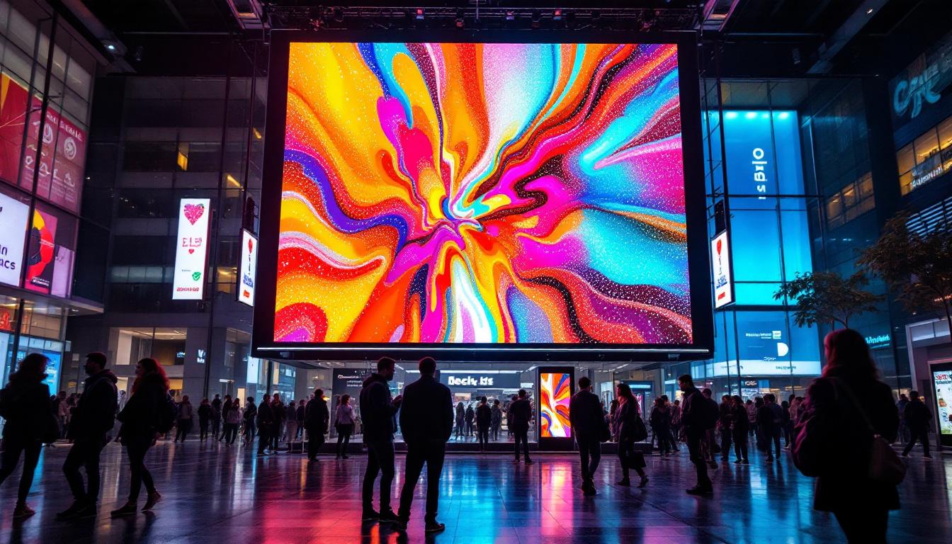
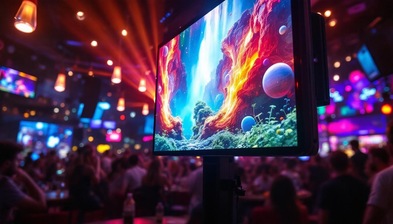
Commercial Signage
Retail stores, shopping malls, and corporate headquarters often feature large LED signs for branding and advertising. These signs typically consist of modular LED panels arranged in rectangular arrays.
Using Revit arrays, designers can quickly model the entire sign, adjusting size and resolution as needed. This approach supports early visualization for client approvals and enables clash detection with building facades and structural elements.
Moreover, the integration of dynamic content management systems with these LED displays allows businesses to change advertisements in real-time, optimizing marketing strategies based on time of day or audience demographics. This capability not only enhances customer engagement but also maximizes the return on investment for businesses by allowing them to tailor their messaging to specific audiences at peak times.
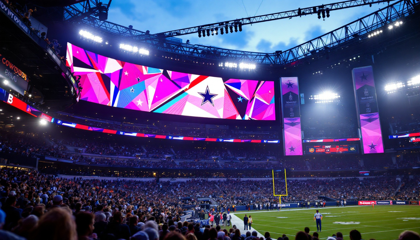
Sports Stadium Scoreboards
Stadiums require massive LED displays with high resolution and brightness. These displays often involve complex arrangements, including curved surfaces and multi-layered arrays.
Revit’s array tool, combined with adaptive components and nested families, can model these complex configurations. This capability helps coordinate with structural engineers and lighting designers, ensuring the scoreboard integrates seamlessly with the stadium design.
Additionally, modern scoreboards are not just for displaying scores; they often incorporate advanced technologies such as augmented reality and interactive features that enhance the spectator experience. By utilizing Revit’s capabilities, designers can simulate these interactive elements during the design phase, allowing for a more comprehensive understanding of how fans will interact with the scoreboard during events.
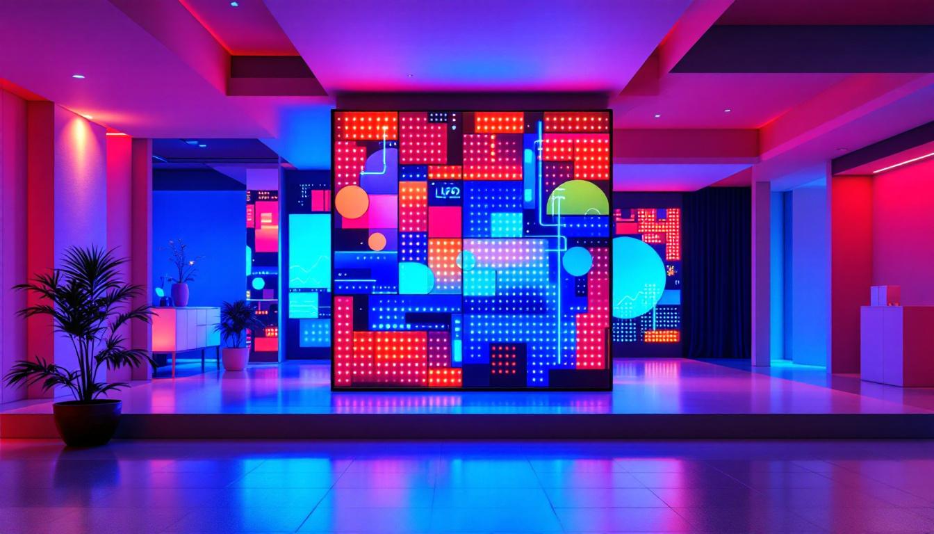
Architectural LED Installations
LED displays are increasingly used as architectural features—dynamic facades, interactive walls, and art installations. These applications often involve irregular shapes and custom layouts.
While arrays are most straightforward for regular grids, Revit’s flexibility allows for combining arrays with custom placement and adaptive components to achieve unique designs. This hybrid approach supports creativity while maintaining modeling efficiency.
Furthermore, the use of LED technology in architectural installations can significantly enhance the environmental performance of buildings. For instance, dynamic facades can adjust their opacity and lighting based on external conditions, contributing to energy efficiency and occupant comfort. By leveraging Revit’s modeling tools, architects can explore various configurations and their impacts on energy consumption, leading to innovative solutions that harmonize aesthetics with sustainability.
Best Practices for Using Arrays in Revit for LED Displays
To maximize the benefits of arrays in Revit for LED display projects, certain best practices should be followed.
Start with a Well-Defined Family
Invest time in creating a parametric LED module family that accurately represents the physical product. Include all relevant parameters and ensure the geometry is optimized for performance.
Use Nested Arrays for Complex Grids
For large displays, create a linear array in one direction, group the elements, and then apply a second array perpendicular to the first. This method reduces model complexity and improves manageability.
Coordinate Early with Other Disciplines
Integrate electrical and structural components early in the design process. Use Revit’s collaboration tools to coordinate with engineers and fabricators, minimizing clashes and rework.
Leverage Revit Schedules and Parameters
Use schedules to quantify LED modules, power requirements, and mounting hardware. Parametric families enable quick updates to these schedules when design changes occur.
Test Array Modifications Carefully
When adjusting array parameters, verify that spacing and alignment remain consistent with physical requirements. Use 3D views and section cuts to inspect the model thoroughly.
Conclusion
Arrays in Revit are a powerful tool for modeling LED displays, enabling designers to efficiently create accurate, scalable, and coordinated models. By understanding the technical aspects of LED modules, array configurations, and integration with building systems, professionals can enhance design quality and streamline project workflows.
Whether designing a commercial sign, a stadium scoreboard, or an architectural LED installation, mastering arrays in Revit is essential for achieving precision and flexibility. Following best practices and leveraging Revit’s parametric capabilities will help ensure successful LED display projects that meet both aesthetic and functional requirements.
Discover LumenMatrix LED Display Solutions
Ready to elevate your architectural, commercial, or entertainment projects with cutting-edge LED displays? Explore LumenMatrix’s comprehensive range of LED display modules, from vibrant Indoor and Outdoor LED Wall Displays to dynamic Vehicle and Sports LED Displays. With our innovative solutions like LED Poster Displays, Floor LED Displays, and Custom configurations, your vision for captivating visual experiences is within reach. Embrace the future of visual communication with our All-in-One and Transparent LED Displays. Check out LumenMatrix LED Display Solutions today and transform your space into a mesmerizing spectacle of light and color.