
In the world of electronics, LED displays are ubiquitous—from digital clocks and calculators to large-scale advertising billboards. Understanding the fundamental differences between common anode and common cathode LED configurations is essential for engineers, hobbyists, and anyone involved in designing or troubleshooting LED-based systems. This article delves into the technical distinctions, practical applications, and design considerations of common anode and common cathode LED displays, helping you make informed decisions in your projects.
Understanding LED Displays: Basics and Terminology
Light Emitting Diodes (LEDs) are semiconductor devices that emit light when an electric current passes through them. An LED display is essentially an arrangement of multiple LEDs configured to show numbers, letters, or graphics. The way these LEDs are wired internally significantly impacts how they are controlled and powered. The versatility of LED displays has made them a popular choice in various applications, from digital clocks and scoreboards to large-scale advertising billboards. Their energy efficiency and long lifespan further enhance their appeal, making them a preferred option in both consumer and industrial settings.
Two common wiring configurations exist for multi-segment LED displays: common anode and common cathode. The terms “anode” and “cathode” refer to the polarity of the LED terminals. The anode is the positive terminal, and the cathode is the negative terminal. In a multi-segment LED, each segment (or individual LED) shares either a common anode or a common cathode connection. Understanding these configurations is crucial for designers and engineers who are working on projects that require precise control over LED displays, as the choice between common anode and common cathode can affect the overall circuit design and component selection.
What Is a Common Anode LED Display?
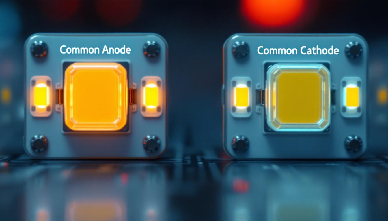
In a common anode LED display, all the anodes of the individual LEDs are connected together and tied to a positive voltage supply. Each segment’s cathode is connected to a control circuit that switches the segment on or off by grounding the cathode. Essentially, to illuminate a segment, the control pin is pulled low (connected to ground), allowing current to flow from the positive common anode through the LED to the cathode. This configuration is particularly advantageous in applications where multiple segments need to be illuminated simultaneously, as it allows for easier control of the segments without requiring complex circuitry. Additionally, common anode displays are often favored in situations where the control logic operates at a low voltage, as they can simplify the design of the driving circuitry.
What Is a Common Cathode LED Display?
Conversely, in a common cathode LED display, all the cathodes of the LEDs are connected together and tied to ground. Each segment’s anode is connected to the control circuit, which switches the segment on or off by applying a positive voltage to the anode. To light up a segment, the control pin is driven high, allowing current to flow from the anode through the LED to the common cathode. This configuration is often preferred in applications where the control circuitry operates at higher voltages, as it can provide a more straightforward interface with microcontrollers and other digital devices. Furthermore, common cathode displays can be advantageous in reducing noise in the circuit, as the grounding of the cathodes can help stabilize the voltage levels across the segments, leading to more consistent brightness and color representation.
Electrical Characteristics and Control Logic
The choice between common anode and common cathode configurations influences the control logic and electrical design of the LED display system.
Control Signal Polarity
In common anode displays, the control signals are active low, meaning that the microcontroller or driver must pull the segment line to ground to turn on the LED segment. This is sometimes referred to as “sinking current.” Conversely, common cathode displays require active high signals, where the control line is driven to a positive voltage to illuminate the segment, known as “sourcing current.”
This difference in control logic can affect the complexity of the driving circuitry. For instance, some microcontrollers or driver ICs are better suited to sourcing current, while others excel at sinking current. Understanding these nuances helps in selecting the appropriate configuration for your application.
Power Consumption and Efficiency
From a power perspective, both configurations can be designed to operate efficiently. However, the choice of configuration can influence the design of current-limiting resistors and the overall power management strategy.
In common anode displays, since the anode is tied to a fixed positive voltage, current-limiting resistors are typically placed on the cathode side. In common cathode displays, resistors are usually placed on the anode side. The position of these resistors and the driving voltage levels can affect the brightness uniformity and power consumption of the display.
Compatibility with Driver ICs
Many LED driver ICs are designed specifically for either common anode or common cathode displays. For example, the popular MAX7219 driver IC is optimized for common cathode 7-segment displays. Using a driver IC incompatible with the display configuration can lead to malfunction or damage.
Therefore, when selecting components, it is crucial to verify the compatibility of the driver IC with the LED display’s common terminal configuration. This ensures reliable operation and simplifies the design process.
Applications and Use Cases
Both common anode and common cathode LED displays have their place in various applications. The choice often depends on the specific requirements of the project, including the type of microcontroller, power supply constraints, and the complexity of the control circuitry.
Common Anode Displays in Practice
Common anode LED displays are frequently used in systems where the control circuitry is better suited to sinking current. For instance, certain microcontrollers with open-drain or open-collector outputs can easily pull lines low, making common anode displays a natural fit.
Additionally, common anode configurations are sometimes preferred in multiplexed display systems where multiple digits share the same anode line, reducing wiring complexity and cost.
Common Cathode Displays in Practice
Common cathode LED displays are often favored in applications where the control signals are designed to source current. Many standard driver ICs and microcontrollers are optimized for sourcing current, making common cathode displays easier to interface with.
They are also common in simple, single-digit displays and devices where straightforward wiring and control logic are priorities.
Choosing Based on Microcontroller and Driver Compatibility
The microcontroller or driver IC’s input/output capabilities often dictate the choice between common anode and common cathode. For example, if a microcontroller’s GPIO pins can sink more current than they source, a common anode display might be more efficient. Conversely, if the pins source current more effectively, a common cathode display is preferable.
Understanding the electrical characteristics of your control hardware is therefore essential to making the right choice.
Design Considerations and Troubleshooting Tips
Designing with either common anode or common cathode LED displays requires careful attention to wiring, current limiting, and control logic to ensure optimal performance and longevity of the LEDs.
Current Limiting Resistors
Regardless of the configuration, it is critical to include appropriate current limiting resistors for each LED segment. These resistors prevent excessive current from damaging the LEDs and help maintain consistent brightness across segments.
The resistor value depends on the supply voltage, LED forward voltage, and desired current. For example, with a 5V supply and a typical red LED forward voltage of 2V at 20mA, a resistor of approximately 150Ω is commonly used.
Multiplexing and Scanning Techniques
In multi-digit displays, multiplexing is often employed to reduce the number of control lines. This technique rapidly switches between digits, lighting one at a time but at a speed imperceptible to the human eye.
Common anode and common cathode displays differ in how multiplexing is implemented. For example, in a common anode multiplexed display, the common anode line is activated for the selected digit, while the cathode lines are controlled to display the desired segments.
Understanding these differences is crucial for designing effective multiplexing circuits and avoiding flicker or uneven brightness.
Troubleshooting Common Issues
Some common problems encountered with LED displays include segments not lighting up, uneven brightness, or excessive power consumption. Diagnosing these issues often involves checking wiring connections, verifying resistor values, and ensuring correct control signal polarity.
For instance, if a segment does not light up in a common anode display, it may be due to the control pin not being pulled low properly. Similarly, in a common cathode display, a segment might fail to illuminate if the control pin is not driven high.
Using a multimeter to measure voltages at the LED terminals and confirming the microcontroller’s output signals can help pinpoint faults quickly.
Summary: Which Configuration Should You Choose?
Choosing between common anode and common cathode LED displays depends on several factors, including the control hardware, driver IC compatibility, power considerations, and application requirements.
Common anode displays are well-suited for systems where the control circuitry sinks current and benefit from simplified multiplexing in certain scenarios. Common cathode displays align better with control circuits that source current and are compatible with many popular driver ICs.
Ultimately, understanding the electrical and logical differences enables designers to select the configuration that best fits their project’s needs, ensuring efficient, reliable, and cost-effective LED display solutions.
Further Resources and Reading
For those interested in deepening their knowledge of LED display design, the following resources provide detailed technical information and practical guidance:
- “LED Display Fundamentals” by Electronics Tutorials – an extensive guide covering LED operation and display types.
- Microcontroller Datasheets – essential for understanding GPIO current sourcing/sinking capabilities.
- Driver IC Manuals such as those for the MAX7219 or TLC5940 – these provide insights into interfacing with common anode or cathode displays.
- Online Electronics Forums – communities like the Electronics Stack Exchange offer valuable discussions and troubleshooting tips.
By leveraging these resources and applying the concepts discussed, engineers and enthusiasts can confidently design and implement LED displays tailored to their specific applications.
Explore Cutting-Edge LED Displays with LumenMatrix
Now that you’re equipped with the knowledge of common anode and common cathode LED displays, take the next step in your project with LumenMatrix. As a pioneer in LED display technology, we offer an extensive range of innovative solutions tailored to your needs. From Indoor and Outdoor LED Wall Displays to specialized options like Vehicle, Sports, and Floor LED Displays, LumenMatrix is committed to transforming your visual communication. Enhance your brand’s presence and captivate your audience with our Custom, All-in-One, and Transparent LED Displays. Check out LumenMatrix LED Display Solutions today and experience the future of digital signage.