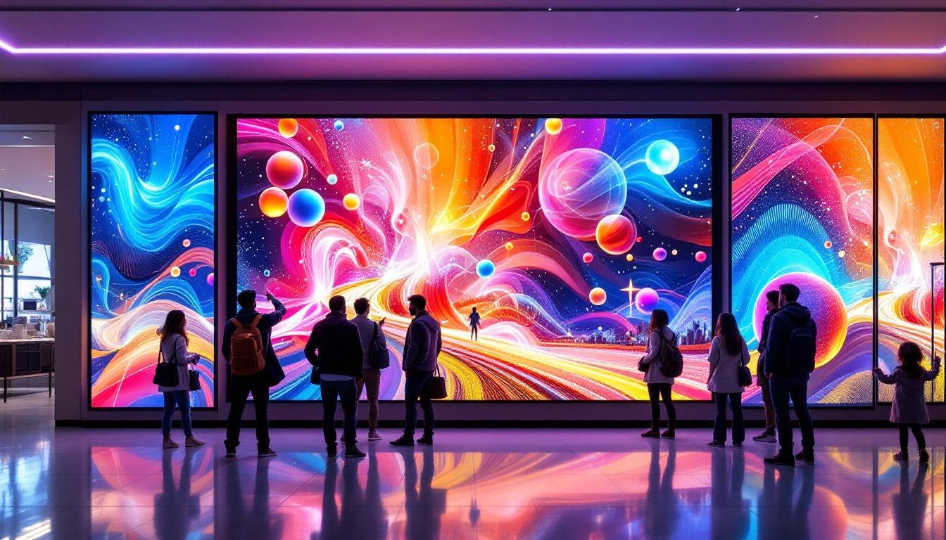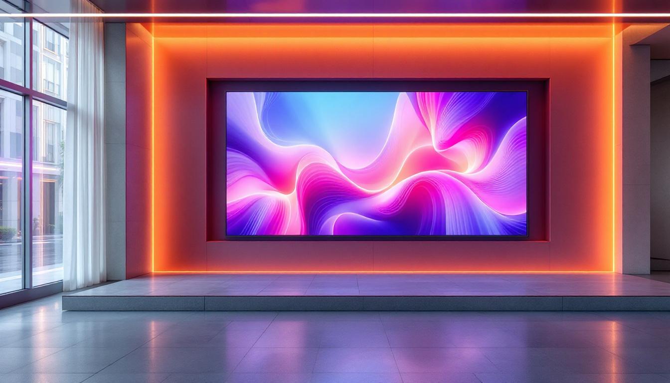
In modern architectural and interior design projects, integrating technology seamlessly into building structures is becoming increasingly important. One such integration is the installation of LED displays within walls, which requires precise planning and execution in Building Information Modeling (BIM) software like Autodesk Revit. This article explores how to create and manage wall openings in Revit specifically for LED displays, covering the technical considerations, workflow strategies, and best practices to ensure accurate modeling and coordination.
Understanding the Importance of Wall Openings for LED Displays
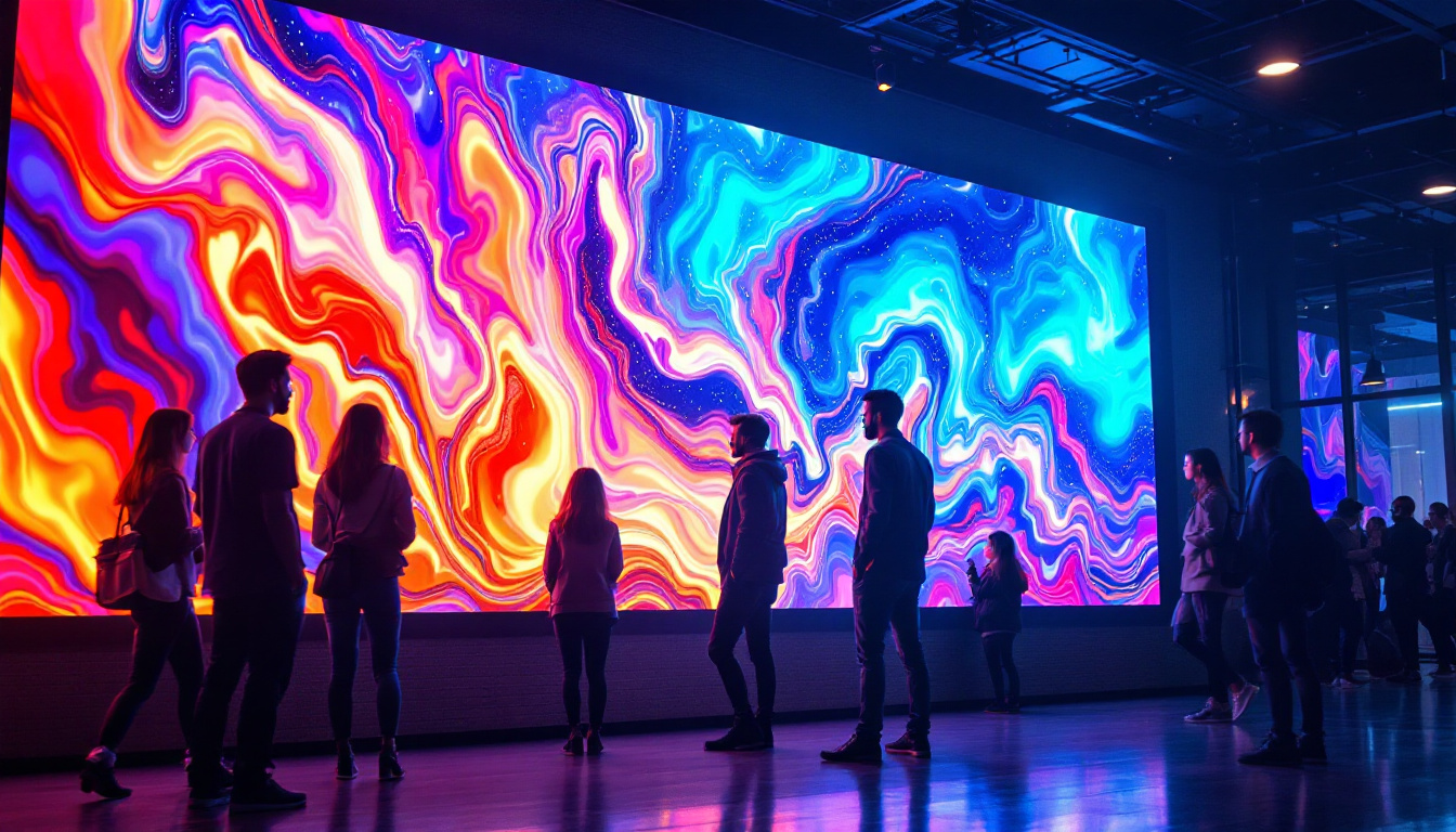
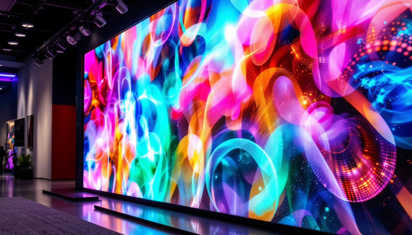
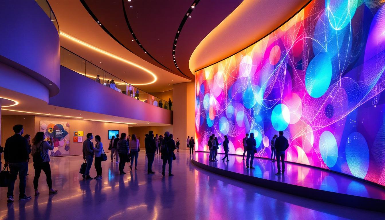
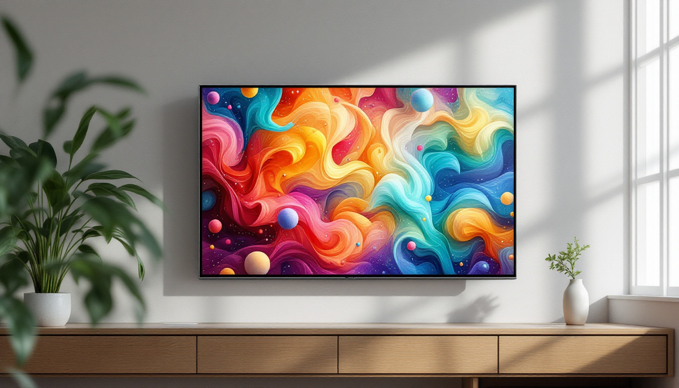
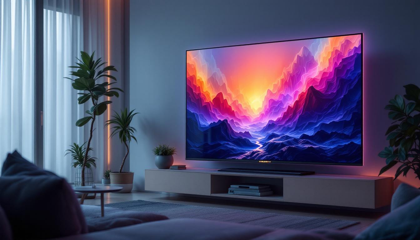
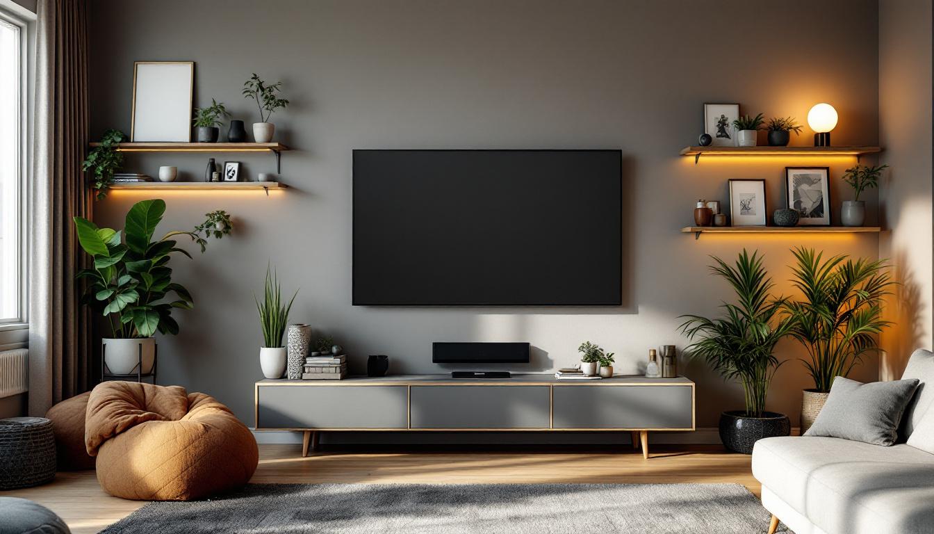
LED displays have become a staple in commercial, retail, and public spaces due to their vibrant visuals and dynamic content capabilities. Whether used for advertising, informational signage, or interactive installations, these displays often need to be embedded within walls to achieve a clean, integrated look.
Creating accurate wall openings in Revit is crucial for several reasons:
- Structural Integrity: Openings must be precisely sized and positioned to avoid compromising the wall’s load-bearing capacity.
- Coordination with MEP Systems: Ensuring that electrical conduits, power supplies, and cooling systems for the LED display are accommodated without clashes.
- Construction Accuracy: Providing clear documentation for contractors to fabricate and install the openings correctly.
- Visual Realism: Enhancing renderings and walkthroughs by showing the LED display as an integrated element rather than an afterthought.
Given these factors, understanding how to model wall openings in Revit tailored for LED displays is essential for architects, engineers, and BIM specialists. The process begins with a thorough analysis of the display’s specifications and the wall’s structural elements. This ensures that the opening not only fits the display but also aligns with the overall design intent of the space. For instance, when integrating a large LED screen into a retail environment, the opening must be designed to optimize visibility from various angles, while also considering the aesthetic flow of the surrounding architecture.
Moreover, the integration of wall openings for LED displays goes beyond mere functionality. It involves a collaborative approach where designers, engineers, and contractors work together to address potential challenges early in the design phase. This collaboration can lead to innovative solutions, such as incorporating adjustable frames or modular systems that allow for easy maintenance and upgrades of the LED technology. Additionally, as LED technology continues to evolve, planning for future upgrades or replacements within the wall structure can save time and resources down the line, making it a forward-thinking investment in the building’s infrastructure.
Technical Considerations for Modeling Wall Openings in Revit
Wall Types and Material Properties
Before creating an opening, it is important to understand the wall type where the LED display will be installed. Revit walls can be basic or compound, consisting of multiple layers such as drywall, insulation, structural components, and finishes. Each layer may have different thicknesses and materials that affect how the opening should be modeled.
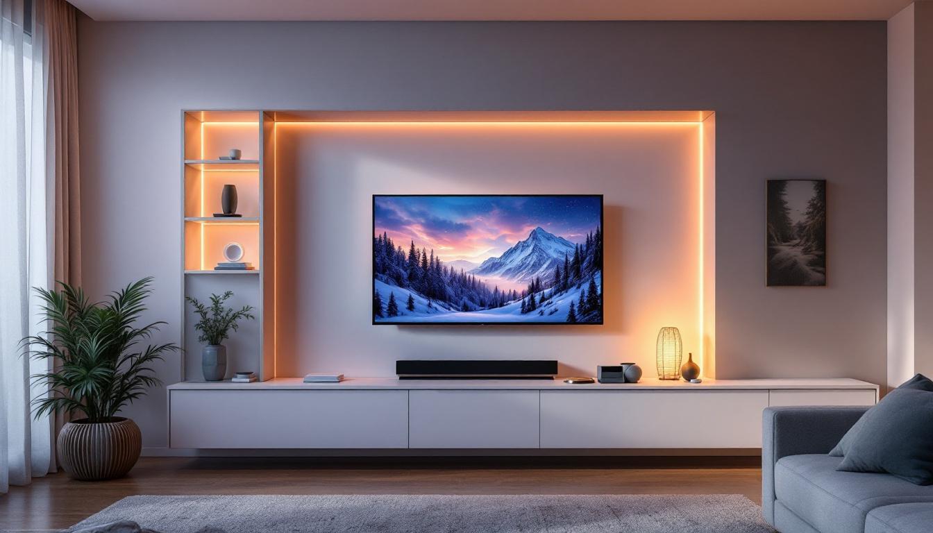
For example, a concrete wall with a gypsum board finish will require an opening that accounts for both the structural core and the finishing layers. This ensures the LED display fits flush with the wall surface and that any necessary framing or reinforcement is planned. Additionally, understanding the thermal and acoustic properties of the wall materials can influence the design of the opening. If the wall serves a specific purpose, such as sound insulation or energy efficiency, the opening must be designed to maintain these properties as much as possible, potentially incorporating acoustic seals or thermal breaks around the edges of the opening.
Opening Size and Placement Accuracy
The dimensions of the LED display dictate the size of the wall opening. It is best practice to obtain precise measurements from the LED manufacturer, including allowances for mounting brackets, ventilation gaps, and cable routing.
In Revit, openings can be created using the Wall Opening tool or by modeling voids within wall families. Positioning the opening accurately in three dimensions—height, width, and depth—is critical to avoid clashes with structural elements or services. Furthermore, it is essential to consider the accessibility of the display for maintenance purposes. This may involve adjusting the height or placement of the opening to ensure that technicians can reach the display easily without requiring extensive scaffolding or ladders, which can complicate future service visits.
Structural and MEP Coordination
Integrating wall openings for LED displays requires close coordination with structural engineers and MEP (Mechanical, Electrical, and Plumbing) teams. Structural engineers need to verify that the opening does not weaken the wall or require additional reinforcement. Meanwhile, MEP professionals must ensure that electrical wiring, power supplies, and cooling systems are planned around the opening.
Revit’s coordination tools, such as clash detection and linked models, facilitate this collaboration by allowing teams to identify and resolve conflicts early in the design process. Additionally, it is beneficial to establish a clear communication protocol among all parties involved, ensuring that any changes in design or specifications are promptly shared. This proactive approach can help mitigate potential delays and ensure that the installation of the LED display proceeds smoothly, adhering to the overall project timeline and budget. Regular design reviews and updates can also help maintain alignment among the various disciplines, fostering a collaborative environment that enhances the final outcome of the project.
Step-by-Step Workflow to Create Wall Openings for LED Displays in Revit
1. Prepare the Wall and LED Display Families
Start by selecting or creating the wall type where the LED display will be installed. Ensure the wall’s layer structure accurately represents the real-world construction.
Next, import or create a family for the LED display. This family should include the display’s physical dimensions, mounting details, and any necessary connectors or ventilation features.
2. Use the Wall Opening Tool
Revit’s Wall Opening tool allows users to cut rectangular or custom-shaped openings directly into walls. To create an opening:
- Go to the Architecture tab and select Wall Opening.
- Draw the opening shape on the wall face, matching the LED display dimensions.
- Adjust the opening’s height and position using the properties palette or temporary dimensions.
This method is efficient for simple rectangular openings but may require additional detailing for complex shapes or multi-layer walls.
3. Employ Void Forms for Complex Openings
For more complex or irregularly shaped openings, creating a void form within a wall family is often preferred. This involves editing the wall family in the Family Editor:
- Open the wall family and create a void extrusion or void sweep with the desired opening shape.
- Cut the void through the wall layers to create the opening.
- Load the updated family back into the project.
This approach provides greater control over the opening’s shape and integration with the wall’s layered structure.
4. Insert the LED Display Family
Once the opening is created, place the LED display family into the opening. Use alignment and snapping tools to position the display flush with the wall surface or recessed as required.
Check for any interference with adjacent elements and adjust the opening or display position as needed.
5. Coordinate with Structural and MEP Models
Link structural and MEP models into the Revit project to perform clash detection. Resolve any conflicts related to the wall opening, such as reinforcing steel placement or conduit routing.
Update the wall opening or LED display placement accordingly to maintain design integrity and constructability.
Best Practices and Tips for Successful LED Display Integration
Early Collaboration Is Key
Engage structural engineers, MEP consultants, and LED display manufacturers early in the design process. Early collaboration helps identify potential issues and allows for design adjustments before construction documentation.
Use Parametric Families for Flexibility
Creating parametric LED display families with adjustable dimensions and mounting options can save time and reduce errors. These families can be easily adapted for different projects or display models.
Document Openings Clearly
Provide detailed schedules and annotations for wall openings in construction documents. Include dimensions, tolerances, and installation notes to guide contractors accurately.
Consider Thermal and Ventilation Requirements
LED displays generate heat and may require ventilation or cooling systems. Ensure that wall openings accommodate these needs without compromising the building envelope.
Leverage Revit Add-Ins and Plugins
Several Revit add-ins specialize in wall openings and coordination management. Utilizing these tools can enhance efficiency and accuracy, especially on large or complex projects.
Case Study: Integrating a Large LED Display Wall in a Retail Store
A prominent retail chain recently undertook a store renovation that included installing a large LED video wall embedded within a feature wall. The project team used Revit to model the wall opening and coordinate all disciplines involved.
The LED display measured 4 meters wide by 2.5 meters high, requiring a precise opening in a composite wall consisting of steel studs, insulation, and gypsum board finishes. The team created a parametric wall opening family to accommodate the display and associated ventilation grills.
Coordination with structural engineers led to the addition of steel reinforcements around the opening to maintain wall integrity. MEP consultants designed a dedicated electrical conduit and cooling system routed through adjacent ceiling spaces.
The final Revit model provided detailed documentation and clash-free coordination, resulting in a smooth installation process and a visually striking LED wall that enhanced the store’s customer experience.
Conclusion
Modeling wall openings for LED displays in Revit requires a thorough understanding of wall construction, precise dimensioning, and multidisciplinary coordination. By following best practices and leveraging Revit’s powerful tools, design teams can ensure that LED displays are integrated seamlessly and safely into building structures.
As LED technology continues to evolve and become more prevalent in architectural design, mastering wall opening techniques in Revit will remain a valuable skill for BIM professionals, architects, and engineers alike.
Discover Cutting-Edge LED Display Solutions
Ready to elevate your architectural designs with the latest in LED technology? LumenMatrix is at the forefront of LED innovation, offering a wide range of solutions that bring walls to life. From engaging Indoor LED Wall Displays to dynamic Outdoor LED Wall Displays, and even specialized options like Vehicle and Sports LED Displays, LumenMatrix has the perfect fit for any project. Embrace the future of visual communication and create immersive environments with our LED display modules. Check out LumenMatrix LED Display Solutions today and transform your space into a captivating visual experience.