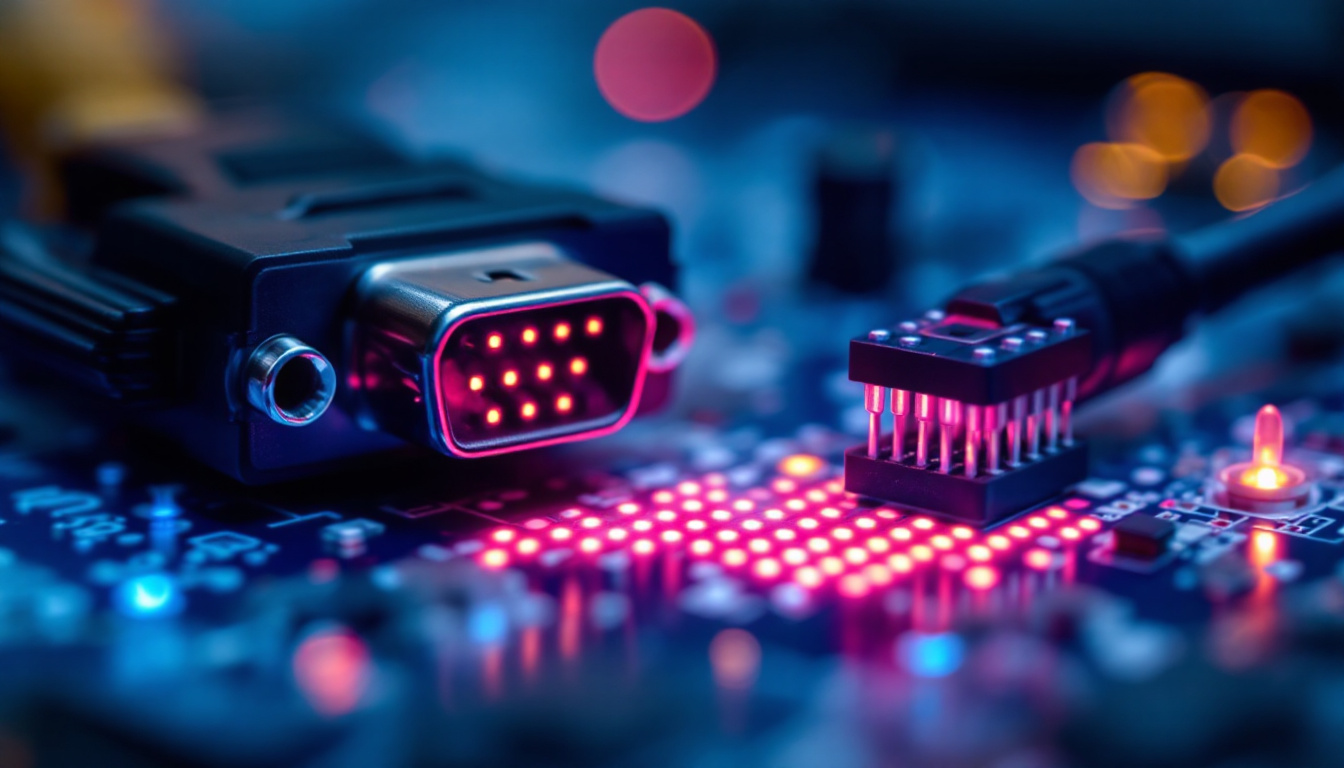
The RS-232 standard has been a cornerstone in serial communication for decades, providing a reliable means of data transmission between devices. While many may think of RS-232 as a relic of the past, its applications remain relevant, particularly in industrial settings, telecommunications, and embedded systems. This article delves into the intricacies of RS-232 pin configuration, specifically focusing on how it interacts with LED displays.
Understanding RS-232: A Brief Overview
RS-232, which stands for “Recommended Standard 232,” was introduced in the 1960s and has since become a widely accepted standard for serial communication. It defines the electrical characteristics and timing of signals, as well as the physical size and pin configuration of connectors.
Typically, RS-232 uses a 9-pin or 25-pin connector, with each pin serving a specific function. The standard allows for point-to-point communication, meaning that it connects one device directly to another. This simplicity has contributed to its longevity, despite the emergence of newer communication protocols.
Key Features of RS-232
One of the main features of RS-232 is its ability to transmit data over relatively long distances—up to 50 feet (15 meters) at lower baud rates. This makes it suitable for various applications, including connecting computers to peripherals like printers and modems.
Additionally, RS-232 supports a range of baud rates, typically from 300 to 115200 bps (bits per second). This flexibility allows it to adapt to different communication needs, making it a versatile choice for many systems. The protocol also includes features such as flow control, which helps manage the pace of data transmission, ensuring that the receiving device can process the incoming data without being overwhelmed.
Common Applications
Despite the rise of USB and Ethernet, RS-232 remains prevalent in specific industries. It is commonly used in industrial automation, where devices like PLCs (Programmable Logic Controllers) and sensors rely on RS-232 for communication. Furthermore, legacy systems in telecommunications still utilize RS-232 for connecting modems and routers.
Its simplicity and reliability make RS-232 an enduring choice for applications that require straightforward serial communication, especially in environments where newer technologies may not be feasible. In medical equipment, for instance, RS-232 is often employed to connect diagnostic devices to computers, allowing for the seamless transfer of patient data. Similarly, in the realm of point-of-sale systems, RS-232 interfaces are frequently used to link cash registers with barcode scanners and receipt printers, showcasing the standard’s versatility across various sectors.
RS-232 Pin Configuration Explained
The pin configuration of RS-232 connectors can vary depending on whether a 9-pin or 25-pin connector is used. Understanding the function of each pin is crucial for establishing proper communication between devices.
9-Pin Connector Configuration
The 9-pin D-sub connector, often referred to as DB9, is the most commonly used configuration in modern applications. Below is a breakdown of the pin assignments:
- Pin 1: DCD (Data Carrier Detect) – Indicates that a carrier signal is present.
- Pin 2: RXD (Receive Data) – The pin used to receive data from the connected device.
- Pin 3: TXD (Transmit Data) – The pin used to send data to the connected device.
- Pin 4: DTR (Data Terminal Ready) – Signals that the device is ready to communicate.
- Pin 5: GND (Ground) – The common ground reference for the connection.
- Pin 6: DSR (Data Set Ready) – Indicates that the connected device is ready to communicate.
- Pin 7: RTS (Request to Send) – Used to indicate that the device wants to send data.
- Pin 8: CTS (Clear to Send) – Indicates that the device is clear to send data.
- Pin 9: RI (Ring Indicator) – Used in modem connections to indicate an incoming call.
Each of these pins plays a vital role in the communication process, particularly in environments where data integrity and reliability are paramount. For instance, the RTS and CTS pins are part of hardware flow control, which helps prevent data loss during transmission by ensuring that the sending device does not overwhelm the receiving device with data it cannot process in real-time. This is particularly important in industrial applications where equipment must operate seamlessly and without interruption, making the correct pin configuration essential for successful integration.
25-Pin Connector Configuration
The 25-pin D-sub connector, or DB25, is an older configuration that was more common in earlier computer systems. While it is less frequently used today, understanding its pin configuration is still important for working with legacy systems. Here are the primary pin assignments:
- Pin 1: GND (Ground) – Common ground reference.
- Pin 2: TXD (Transmit Data) – Used to send data.
- Pin 3: RXD (Receive Data) – Used to receive data.
- Pin 4: RTS (Request to Send) – Indicates a request to send data.
- Pin 5: CTS (Clear to Send) – Indicates that the device is ready to receive data.
- Pin 6: DSR (Data Set Ready) – Indicates that the device is ready.
- Pin 7: DCD (Data Carrier Detect) – Indicates the presence of a carrier signal.
- Pin 8: RI (Ring Indicator) – Used in modem connections.
- Pin 20: DTR (Data Terminal Ready) – Indicates that the terminal is ready to communicate.
In addition to these basic functions, the DB25 connector supports a wider range of signals, making it suitable for more complex communication setups. For example, it can accommodate additional control signals that are useful in multi-device configurations, such as printers and other peripherals. The versatility of the DB25 connector allowed it to be a standard in early computing, facilitating connections in a variety of environments, from office settings to industrial machinery. Despite its decline in favor of more compact connectors, the principles behind its pin configuration continue to inform the design of modern communication interfaces.
Connecting RS-232 to LED Displays
LED displays have become increasingly popular for various applications, from simple indicators to complex graphical displays. Understanding how to connect RS-232 to LED displays is essential for ensuring proper communication and functionality.
Types of LED Displays
There are different types of LED displays, including seven-segment displays, matrix displays, and graphic displays. Each type has its own method of interfacing with an RS-232 signal, which can affect how data is sent and received.
Seven-segment displays are commonly used for numerical outputs, while matrix displays can show alphanumeric characters and graphics. Graphic displays, on the other hand, offer more versatility and can represent complex data visually. The choice of display type will influence the design of the RS-232 communication protocol.
Wiring and Configuration
When connecting an RS-232 interface to an LED display, proper wiring is crucial. The TXD pin from the RS-232 connector should be connected to the RXD pin of the LED display, while the RXD pin of the RS-232 should connect to the TXD pin of the LED display. Additionally, a common ground connection is necessary to ensure signal integrity.
It is also essential to configure the baud rate and other communication parameters to match between the RS-232 device and the LED display. Mismatched settings can lead to communication errors, causing the display to malfunction or show incorrect information.
Common Issues and Troubleshooting
When working with RS-232 connections and LED displays, various issues may arise. Understanding common problems and their solutions can save time and frustration during setup and operation.
Signal Integrity Problems
Signal integrity issues can occur due to long cable lengths, poor connections, or electromagnetic interference. To mitigate these problems, ensure that the cables used are of high quality and that connections are secure. Additionally, using shielded cables can help protect against interference.
Configuration Mismatches
As mentioned earlier, configuration mismatches between devices can lead to communication failures. It is vital to double-check settings such as baud rate, parity, and stop bits on both the RS-232 device and the LED display. Ensuring that these parameters match will facilitate smooth communication.
Best Practices for RS-232 and LED Display Integration
Integrating RS-232 with LED displays can be a straightforward process if best practices are followed. These practices can help ensure reliable performance and longevity of the system.
Use Quality Components
Investing in high-quality connectors, cables, and displays can significantly reduce the likelihood of issues. Quality components are less prone to failure and can withstand the rigors of industrial environments.
Document the Configuration
Keeping detailed documentation of the pin configuration, wiring diagrams, and communication settings can be invaluable for troubleshooting and future maintenance. This documentation can serve as a reference for anyone working with the system, ensuring consistency and clarity.
Conclusion
The RS-232 standard remains a relevant and effective means of communication in various applications, particularly when interfacing with LED displays. Understanding the pin configuration, proper wiring techniques, and troubleshooting methods is essential for successful integration.
By adhering to best practices and maintaining high-quality components, users can ensure reliable performance and longevity of their RS-232 and LED display systems. As technology continues to evolve, the principles of RS-232 communication will likely remain a foundational element in the world of serial data transmission.
In conclusion, whether for industrial automation, telecommunications, or embedded systems, mastering RS-232 pin configuration and its application with LED displays is a valuable skill that can enhance the functionality and reliability of numerous devices.
Discover Cutting-Edge LED Display Solutions with LumenMatrix
Ready to take your visual communication to the next level? LumenMatrix offers a comprehensive range of LED display technologies that are perfect for any application, from vibrant indoor and outdoor displays to innovative vehicle and sports solutions. Whether you’re looking to create an immersive experience with a Floor LED Display or seeking the versatility of an All-in-One LED Display, LumenMatrix has the state-of-the-art modules to bring your vision to life. Elevate your brand visibility and captivate your audience with our Custom LED Displays and Transparent LED solutions. Check out LumenMatrix LED Display Solutions today and see how we can help you share your message with impact and clarity.

