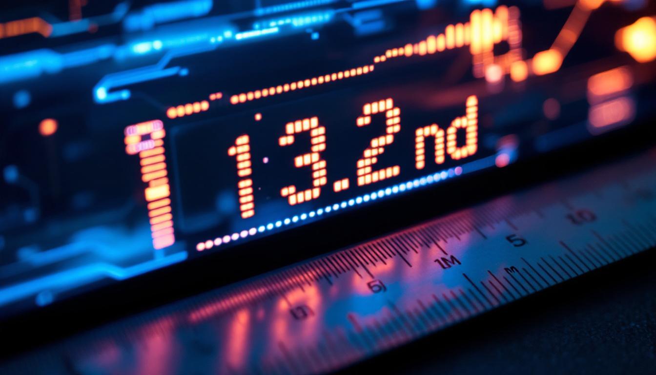
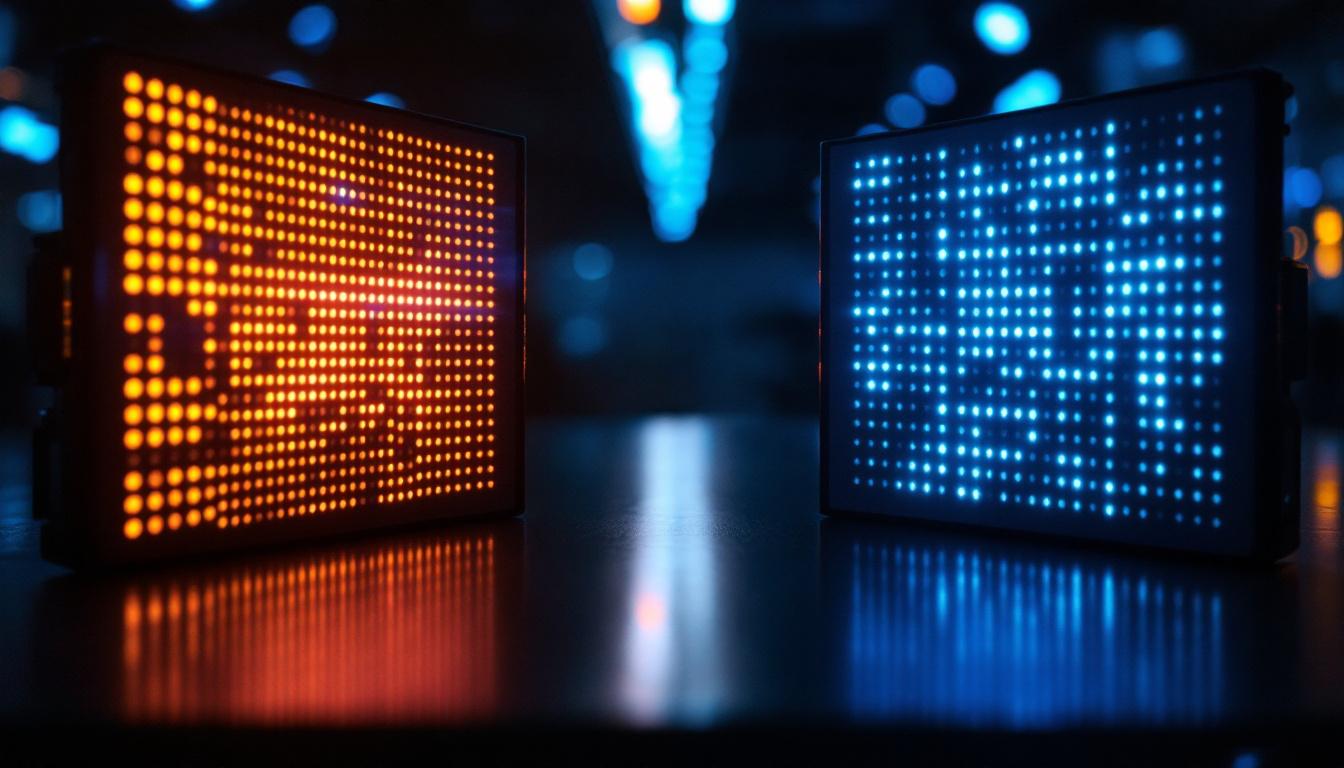
LED displays have become ubiquitous in modern technology, from digital billboards and traffic signals to sophisticated screens in smartphones and wearable devices. Understanding the fundamental electrical configurations behind these displays is crucial for engineers, hobbyists, and anyone involved in electronics design. Two primary configurations dominate the LED display world: common cathode and common anode. This article delves deep into these configurations, explaining their differences, applications, advantages, and how to choose the right one for your project.
Understanding LED Display Basics
Before diving into the nuances of common cathode and common anode LED displays, it’s essential to grasp the basics of how LEDs work and how they are arranged in displays. An LED (Light Emitting Diode) is a semiconductor device that emits light when an electric current passes through it. In LED displays, multiple LEDs are arranged in a matrix or segment format to represent numbers, letters, or images.
Each LED has two terminals: the anode (positive) and the cathode (negative). The direction of current flow through these terminals determines whether the LED lights up. In a display, multiple LEDs share connections to simplify wiring and control, leading to the common cathode or common anode configurations.
LED Segment Displays
Segment displays, such as the popular 7-segment displays, use multiple LEDs arranged in segments to represent digits. Each segment corresponds to an LED that can be turned on or off independently. By controlling which segments light up, the display can show numbers 0-9 and some letters.
In these displays, the LEDs are wired in a way that either all the cathodes are connected together (common cathode) or all the anodes are connected together (common anode). This wiring scheme affects how the display is driven electronically.
Common Cathode LED Displays
In a common cathode LED display, all the cathode terminals of the LEDs in the display are connected together and typically connected to the ground (0V). Each individual LED segment’s anode is connected to a control pin that supplies a positive voltage to light up the segment.
How Common Cathode Displays Work
Since the cathodes are tied to ground, turning on a segment involves applying a positive voltage to its anode. This forward-biases the LED, allowing current to flow from the anode to the cathode, causing the LED to emit light.
Controlling the display involves setting the control pins to a high voltage (usually 5V or 3.3V) to illuminate the desired segments and setting others to low or floating to keep them off.
Advantages of Common Cathode Displays
- Simplified Grounding: Having a common ground simplifies the circuit design, especially when interfacing with microcontrollers that share a common ground reference.
- Compatibility with NPN Transistors and N-Channel MOSFETs: These devices, commonly used as switches in electronic circuits, work more efficiently when switching the positive side of the load, which is the case in common cathode configurations.
- Easier to Interface with Certain ICs: Many driver ICs and microcontrollers are designed to source current (provide positive voltage), making common cathode displays a natural fit.
Applications of Common Cathode LED Displays
Common cathode displays are widely used in digital clocks, calculators, and embedded systems where microcontrollers source current to the display. Their straightforward wiring and compatibility with common switching components make them a popular choice for hobbyists and professionals alike.
Common Anode LED Displays
In contrast, a common anode LED display connects all the anode terminals of the LEDs together, usually to a positive voltage supply. Each LED segment’s cathode is connected to a control pin that sinks current to ground to light the segment.
How Common Anode Displays Work
With the anodes tied to a positive voltage, illuminating a segment requires pulling its cathode to ground. This reverse control means the control pins are active low—setting a pin to low turns the LED on, while setting it high turns it off.
Driving common anode displays often involves sinking current through the control pins, which can affect the choice of driving components and microcontroller pins.
Advantages of Common Anode Displays
- Compatibility with PNP Transistors and P-Channel MOSFETs: These devices are better suited for switching the positive side of the circuit, which aligns with common anode wiring.
- Lower Power Consumption in Certain Configurations: In some multiplexed display designs, common anode displays can reduce power consumption by controlling the ground side of the LEDs.
- Preferred in Some Multiplexing Schemes: Certain multiplexing driver ICs and techniques are optimized for common anode displays.
Applications of Common Anode LED Displays
Common anode displays are often found in industrial equipment, automotive dashboards, and multiplexed display systems where current sinking is preferred or required. Their wiring suits specific driver ICs and power management strategies.
Comparing Common Cathode and Common Anode Displays
Choosing between common cathode and common anode displays depends on the application, the driving circuitry, and the desired electrical characteristics. Below is a detailed comparison to help clarify the differences.
Electrical Characteristics
| Feature | Common Cathode | Common Anode |
|---|---|---|
| Common Terminal | Cathode (Negative) | Anode (Positive) |
| Control Pin Logic | High to turn ON | Low to turn ON |
| Typical Driver Type | Current sourcing | Current sinking |
| Microcontroller Pin Usage | Source current (output HIGH) | Sink current (output LOW) |
| Switching Components | NPN transistors, N-channel MOSFETs | PNP transistors, P-channel MOSFETs |
Driving Complexity and Circuit Considerations
Common cathode displays are generally easier to drive with microcontrollers that source current, as many microcontroller pins are designed to output a positive voltage. Conversely, common anode displays require sinking current, which may necessitate additional components or specific driver ICs.
Multiplexing—a technique used to control multiple LEDs with fewer pins—is affected by the choice of common terminal. Some multiplexing ICs are designed specifically for common anode or common cathode displays, so compatibility must be checked before selection.
Power Consumption and Efficiency
Power consumption differences between the two configurations are generally minimal but can become significant in large, multiplexed displays. Common anode displays may offer slight efficiency advantages in certain multiplexing schemes by reducing switching losses on the positive side.
Practical Considerations When Choosing Between Common Cathode and Common Anode
Microcontroller and Driver Compatibility
One of the most critical factors in choosing between common cathode and common anode displays is the compatibility with the microcontroller or driver IC. Many popular microcontrollers, such as those in the Arduino or Raspberry Pi ecosystems, can source current more easily than they sink it, making common cathode displays a natural choice.
However, if using specialized driver ICs like the MAX7219 or TLC5940, which are designed to sink current, common anode displays might be preferable. Always consult the datasheets of your components to ensure compatibility.
Wiring and PCB Design
The wiring complexity can differ between the two types. Common cathode displays often simplify grounding schemes, while common anode displays require a stable positive voltage rail. In PCB design, this can influence trace layout, power distribution, and noise considerations.
Application Environment
Environmental factors such as voltage levels, power availability, and electromagnetic interference can influence the choice. For example, automotive applications often prefer common anode displays due to the vehicle’s electrical system design and the need for robust current sinking capabilities.
Tips for Working with LED Displays
Use Current-Limiting Resistors
Regardless of the configuration, always use appropriate current-limiting resistors to prevent damage to the LEDs. The resistor value depends on the LED forward voltage, supply voltage, and desired current. Typical LED currents range from 10mA to 20mA.
Consider Multiplexing for Large Displays
For displays with many LEDs, multiplexing reduces the number of control pins needed. Multiplexing techniques require careful timing and driver selection to avoid flickering and ensure brightness uniformity.
Test the Display Before Final Integration
Always test the LED display with your chosen configuration and driver circuit before final assembly. This helps identify wiring errors, compatibility issues, and brightness inconsistencies early in the development process.
Conclusion
Understanding the differences between common cathode and common anode LED displays is fundamental for anyone working with LED technology. Each configuration offers unique advantages and challenges related to wiring, driving methods, and application suitability.
Common cathode displays are generally easier to interface with microcontrollers that source current, making them popular in hobbyist and embedded systems. Common anode displays, on the other hand, are favored in industrial and automotive environments where current sinking and specific driver IC compatibility are crucial.
Careful consideration of your project’s requirements, available components, and power management strategies will guide the optimal choice between these two configurations. With this knowledge, designing efficient, reliable, and visually appealing LED displays becomes a more straightforward and rewarding endeavor.
Explore Cutting-Edge LED Displays with LumenMatrix
Now that you’re equipped with the knowledge of common cathode and anode LED displays, take the next step in your project with LumenMatrix. As a pioneer in LED display technology, LumenMatrix offers a wide array of innovative solutions, from Indoor and Outdoor LED Wall Displays to specialized options like Vehicle, Sports, and Floor LED Displays. Whether you’re looking to enhance brand visibility or create immersive visual experiences, our LED display modules are designed to captivate and engage. Check out LumenMatrix LED Display Solutions today and see how we can help you communicate your message with unparalleled impact and clarity.